Wednesday 8 August 2012


USBasp - USB programmer for Atmel AVR controllers


About The Programmer
USBasp is a USB in-circuit programmer for Atmel AVR controllers. It simply consists of an ATMega48 and 

ATMega88 an ATMega8 and a couple of passive components. The programmer uses a firmware-only USB driver,
 no special USB controller is needed.

Features

  • Works under multiple platforms. Linux, Mac OS X and Windows are tested.
  • No special controllers or smd components are needed.
  • Programming speed is up to 5kBytes/sec.
  • SCK option to support targets with low clock speed (< 1,5MHz).


Simple Steps to made This programmer

Step 1:-

Download:Firmware and circuit
The following packages include circuit and firmware.
Firmware is the software which going to be burn into programmer's microcontroller, this firmware have code to 

enable the programmer to communicate with pc via usb and target microcontroller.

Click This link to dwonload the Firware and circuit     
usbasp.2011-05-28.tar.gz (519 kB )      UPDATED
, installing and using USBasp.

Schematic USB AVR Mircrocontroller progammer

Step 2:- 

Buy The parts You need

Part                   Descirption           Qty
ATMEGA8             Microcontroller           1
3.6 Volts              Zeaner Diode                 2
22pf                      Capacitor                       2             
100nf                    Capacitor                       1    
4.7uf                     capacitor                        1
12Mhz                  Crystal                             1 
10K                        Resistance                      1
1K                           Resistance                     3
68ohm                  Resistance                      2
2.2K                       Resistance                      1
LED                        Led  (Red & Geen)        2
USB connector                                             1
USB Cable                                                     1    
3 Way dip switch                                         1       


Step 3:-


 PCB and Part Soldering:-

    You can create your own pcb using any PCB editor like eagle, OR you can solder the circuit a general purpose
 pcb,    
A Genral Purpose  PCB
USB AVR Programmer PCB Created by Me For your use
USB AVR  Programmer pcb


Step 4:-

Getting The Atmega8 Microcontroller Ready To be used as a programmer:-
Getting the atemega8 microcontroller ready to be inserted into the newly soldered pcb ,and start working. you 
have to burn the firmware which you just downloaded in the Step 1   into the atmega8 microcontroller.  you can use
 the serial avr programmer to get this job done. click here to know about how to make a serial avr progammer and 
how to program the atmega8 by using a serial avr programmer. 

Note:- Make sure you burn the right fuse bit configration along with the firmware into atmega8 microcontroller
for atemega8   the fuse bit are
atmega8        HFUSE=0xC9     LFUSE=0xEF


Step 6:-

Driver installation on a PC:-

            At the first time when you connect your programmer to the pc your programmer will be dected as usbasp 
and you have to provide a proper path for drivers to be installed.
USB AVR prorammer Dected By the widnows
Give the Instruction for a specfic location driver installation
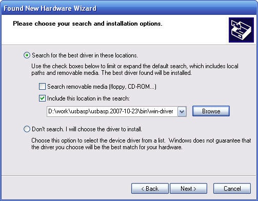
Give the path for driver to be installed
            
USB AVR Programmer installed

USB AVR programmer is being connected and shown in device manager

On Linux and MacOS X no kernel driver is needed.
Windows requires a driver for USBaspusbasp-windriver.2011-05-28.zip (274 kB)

Note: Windows Vista/7 x64 now support with new driver . update your drive with new one..

Step 6:-

Programming the other microcontrollers:-

You can use any of these software to burn the hex file in to the traget microcontrollers.
  • AVRDUDE supports USBasp since version 5.2.  , (A comand line tool) 
  • BASCOM-AVR supports USBasp since version 1.11.9.6. 
  • Khazama AVR Programmer is a Windows XP/Vista GUI application for USBasp and avrdude.
  • eXtreme Burner - AVR is a Windows GUI Software for USBasp based USB AVR programmers


Hardware

Schematic


Connections to the traget microcontroller:-

        * you can programe many microcontroller by using this schematic , all you need to do is that

 find out the data sheet of that mcu you want to program and check the pin configration. and the
 look for PIN MOSI MISO SCK and Reset , the connection will be as follows


Connectors 

USB B type female Connector


10 PIN IDC connector (which shown in the schematic)
     

Monday 6 August 2012


RF module based Remote control (DTMF IC)

        Remote controls are  part of an electronics device used for operating the device remotely. Remote control has continuously evolved and advanced over recent years.The technologies like bluetooth connectivity, motion sensor enabled capabilities and voice control have been included to remote controls.
    
        Here we are going to build a remote control. This remote control could be used for controlling  robo cars, helicopters or for switching home appliances.Normal remote controls use IR transmission,but in this case RF  transmission is used. Transmission through RF is better than IR (infrared) because of many reasons. Firstly, signals through RF can travel through larger distances making it suitable for long range applications. Also, while IR mostly operates in line-of-sight mode, RF signals can travel even when there is an obstruction between transmitter & receiver. Next, RF transmission is more strong and reliable than IR transmission.
  • Component required :
  1. RF  module:                                                                                                                                         For the transmission of control signals (here DTMF signals) we need a RF transmitter and a receiver. FM transmitter and receiver pair or any kind of RF TxRx module will do. In this remote control ASK modulation based RF transmitter & receiver pair are used for transmitting signals .                                                                 .
  2. IC UM91214b( DTMF TONE GENERATOR):                                                                       This is a single single chip IC with an on-chip oscillator for a 3.58Mhz crystal.This is capable of generating Dialing Pulse(DP) and Dual Tone Multi Frequency(DTMF).But we don't need to be bothered about DP generation.All you need is just to generate DTMF signals.A keypad interface is necessary to generate different DTMF signals.The advantage of using UM91214b is its inbuilt keypad interface facility. You just have to connect the  keypad pins to UM91214's Row & Column pins.    UM91214 datasheet from  Here
                 A simple circuit of Um91214 for the purpose of generating only dtmf  is shown:


            Whenever a keypad button is pressed, a DTMF tone is generated on pin7 accordingly. To check whether DTMF tone is being generated or not, simply just connect a 8ohm speaker,press a button and hear the tone.
           

          3. KEYPAD :
              DTMF keypad is available in market. You can make one for yourself. It is easy.the Interconnections of
              a  4x4 keypad is shown here:


    N.B. : UM91214 is compatible for 4x4 matrix keypad.But pressing 16th button won't generate any DTMF tone,it is for redialing,we don't need  this function,we can omit the column for ABCD.

          4.   A 3.58MHZ crystal .


          5.   DTMF decoder IC:
                Upon receiving the DTMF tone from the RF receiver we need to decode it to binary or bcd. A commonly used DTMF decoder ic is cm8870 or MT8870 or XX9370. IC XX8870 takes DTMF tone as input, decodes the tone to binary and outs it to its pin11 to pin14.  datasheet of MT8870 from here

    Circuit diagram for cm8870 is shown bellow:


              In this picture pin11 to pin14 (named as D0,D1,D2,D3) are  output pins,if the DTMF tone for key1 is pressed output will be 0001(pin14=0,pin13=0,pin12=0,pin11=1) 


    Key ToneOutput Logic
    D3(pin14)D2(pin13)D1(pin12)D0(pin11)
    10001
    20010
    30011
    40100
    50101
    60110
    70111
    81000
    91001
    01010
    *1011
    #1100
    A1101
    B1110
    C1111
    D0000
              

             N.B. For desired output, the input gain of CM8870 has to be adjusted. It can be done by varying the resistances connected to pin2 and pin3.


    • Circuit diagram of the transmitter part of the remote control :

    • Circuit diagram of  receiver part of the remote control :

    DTMF

    What is DTFM ?

             DTMF stands for dual tone multi frequency. It is used in analog telephone system for signaling. It is better known as Touch-tone.

    Working principle :

             For DTMF signaling there is always a keypad. When you press a button on the keypad, a path is completed and generates two different tones simultinuously. One is Row tone another isColumn tone. In telephone system, after each button press a 'row tone' and a 'column tone' is send to the telephone exchange, they decodes these tones and identifies which number you have pressed by dialing these tones and switch your call to the number. The same thing is done by the receiver circuitry at called party to identify the calling party(your number).
             For each column and each row a unique frequency is assigned. The figure bellow shows how they are assigned to the rows and columns. Lets take an example, suppose you have pressed 7, so the 'row tone' frequency  for 7 is 852hz and 'column tone' frequency for 7 is 1209hz, these two tone is sent over the telephone line.
             pressing the button 3 will generate 697hz and 1477hz.


    1
    2
    3
    697     Hz
    4
    5
    6
    770 Hz
    7
    8
    9
    852 Hz
    *
    0
    #
    941 Hz
    1209 Hz
    1336 Hz
    1477 Hz


    Special DTMF tones

             There are four more special DTMF tones named as A,B,C,D. To supprt these extra four buttons DTMF keypad has an extra column, the frequency assigned to this column is 1633hz.

    1
    2
    3
    A
    697 Hz
    4
    5
    6
    B
    770 Hz
    7
    8
    9
    C
    852 Hz
    *
    0
    #
    D
    941 Hz
    1209 Hz
    1336 Hz
    1477 Hz
    1633 Hz

    How a DTMF tone look like on CRO screen ?

             Suppose you have pressed 3, corresponding tones are 697hz and 1477hz, they will super-impose and will look like this:
    File:MultiTone1.png


    Download a DTMF keypad for your pc from here DTMF.ZIP